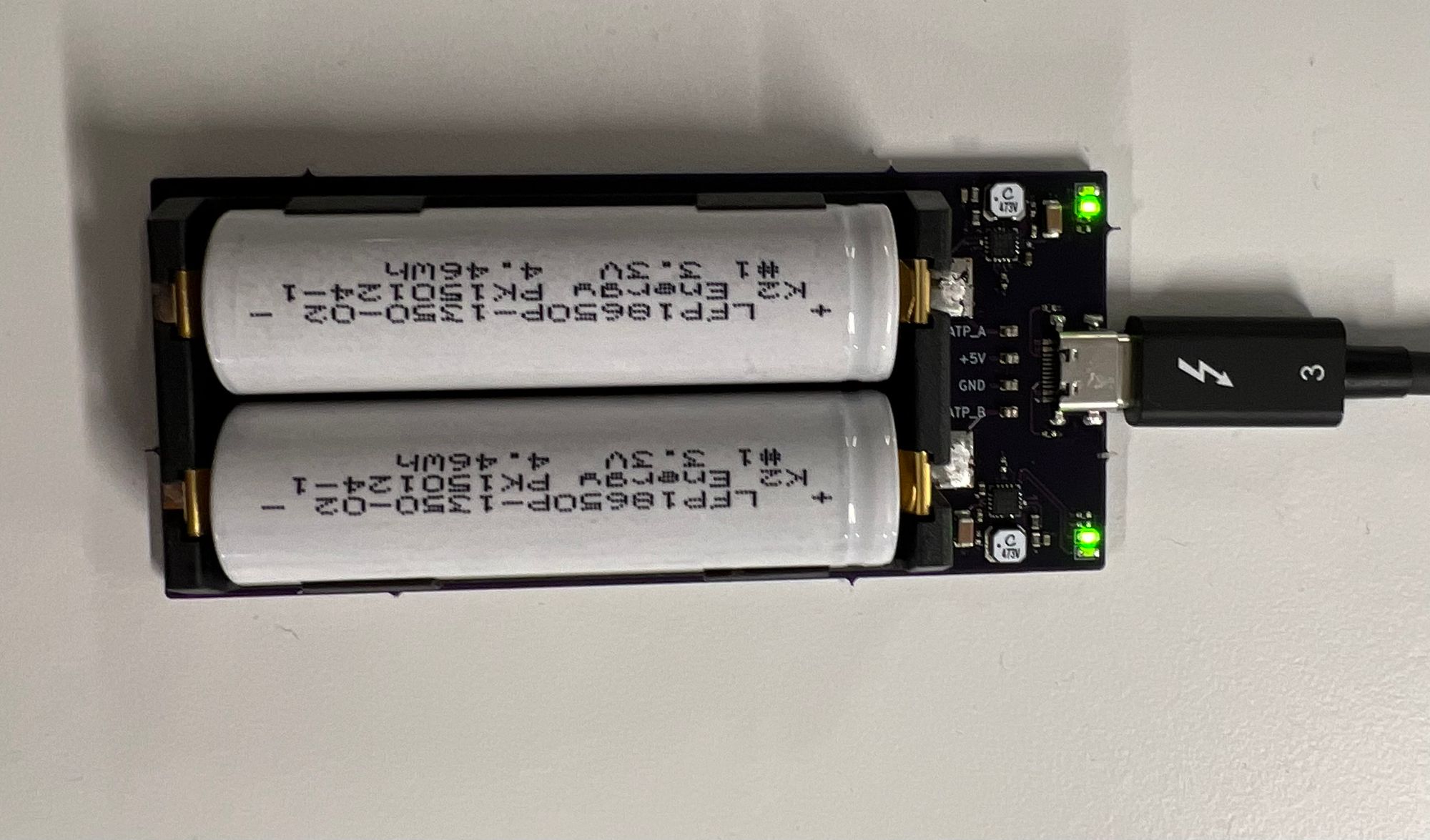
USB-C Powered Dual Slot LiFeP04 18650 Charger
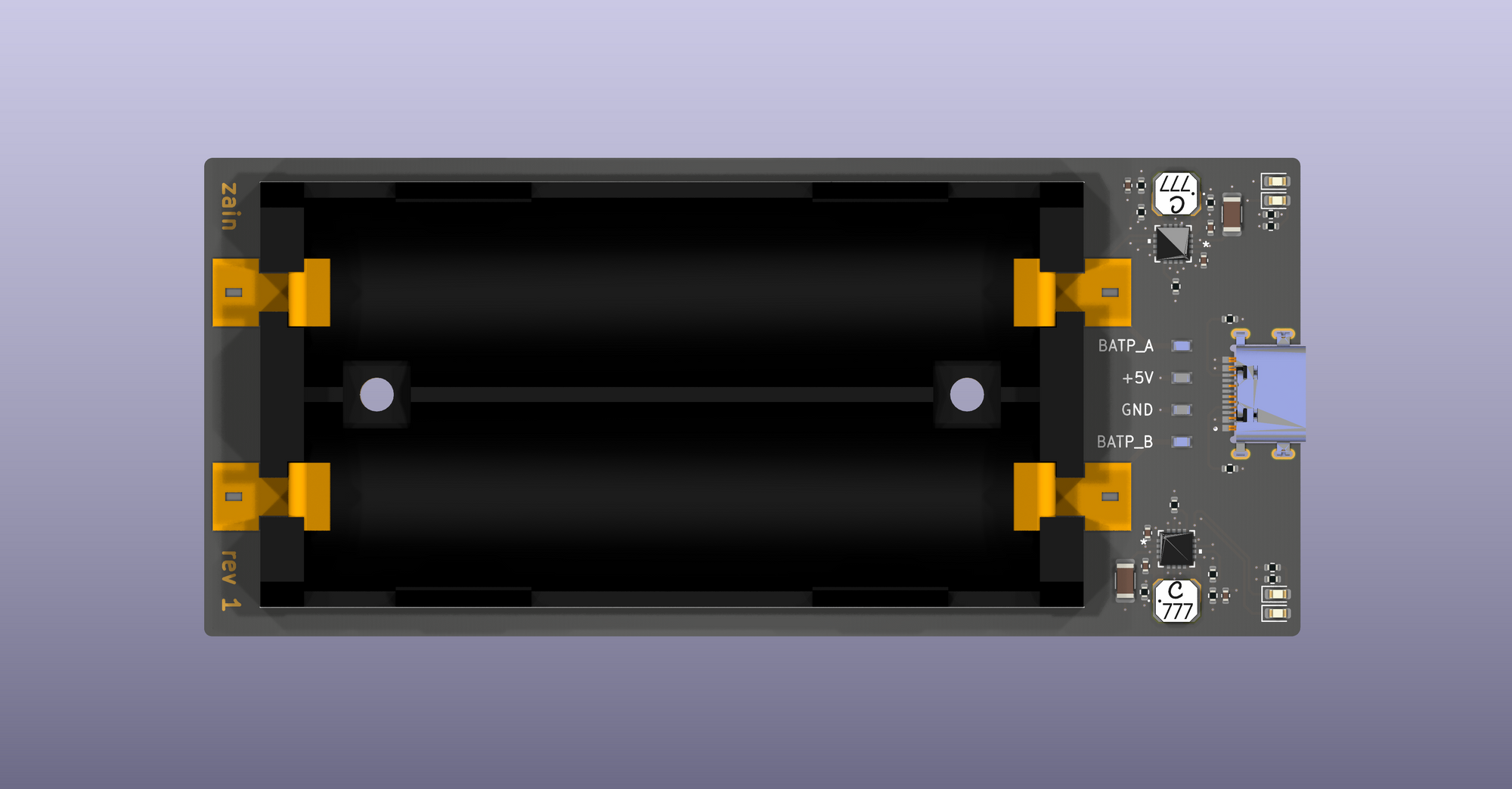
See the files on GitHub.
A couple of years ago, I was gifted about 50 unused K2 Energy LiFeP04 cells, originally intented to be used in autoclavable surgical instruments. They were gifted to my university's solar car team, who were unable to use the cells due to their low-capacity-but-high-punch nature, exactly the opposite of what a long distance solar car needs.
I also have a bit of an obsession with converting nearly everything I own to USB-C, and wanted to build a charger using quality parts. The charger is based on 2x Linear Technology LTC4121 synchronous step down lithium battery charger ICs, with a maximum charge current of 400mA. Since we are charging two cells up to about 3.65v each, we should theoretically only ever see a maximum current of a little over 600mA at the 5v USB input. In reality, charging current drops hard after the battery reaches about 3.4v, so even 600mA is more than what we should ever see.
Schematic

This charger schematic is copied twice into the design, and is a perfect reflection of the typical non-MPPT application in the LTC4121 datasheet. Routing this board isn't super sensitive save for the main switching inductor and a few of the caps. It's worth keeping the feedback resistor group tightly placed and routed as well. The datasheet is very clear on routing specifics for this IC, and I followed the instructions closely to avoid any excess EMC issues (maybe one day I'll actually be able to measure this).
Routing

Since I am only making a few of these I went with Coilcraft LPC4018 series shielded inductors. These have the benefit of being lower tolerance than cheaper alternatives, and also have a great package for pairing with this particular charging IC. The inductor pins match up nicely with the Linear Technology chip, making decent routing easy.
Testing
In order to monitor the cell charge rate, I added some clip on test points from TE Connectivity. These made it super easy to clip in a Saleae logic analyzer to get a good sense of the charge curve.
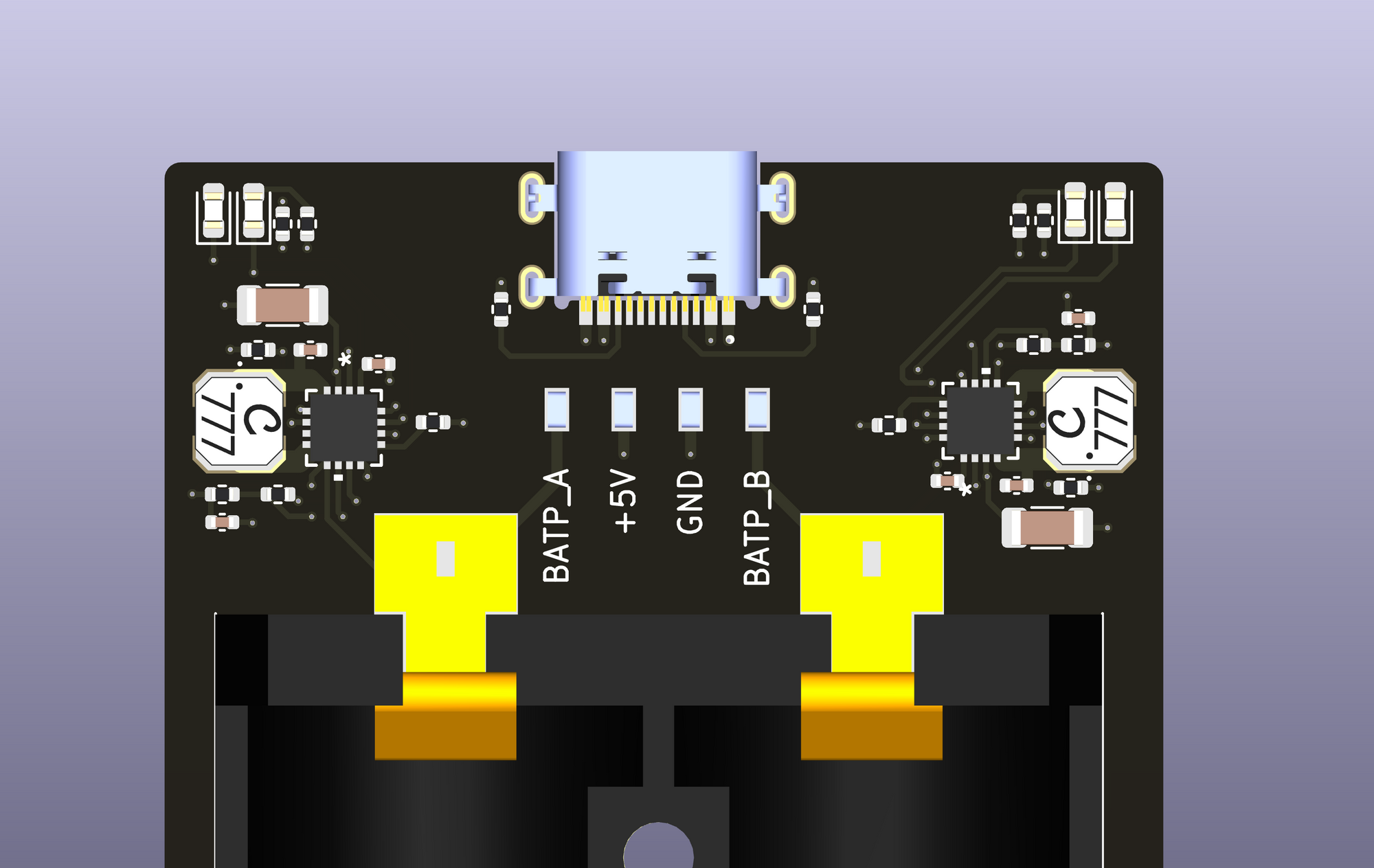
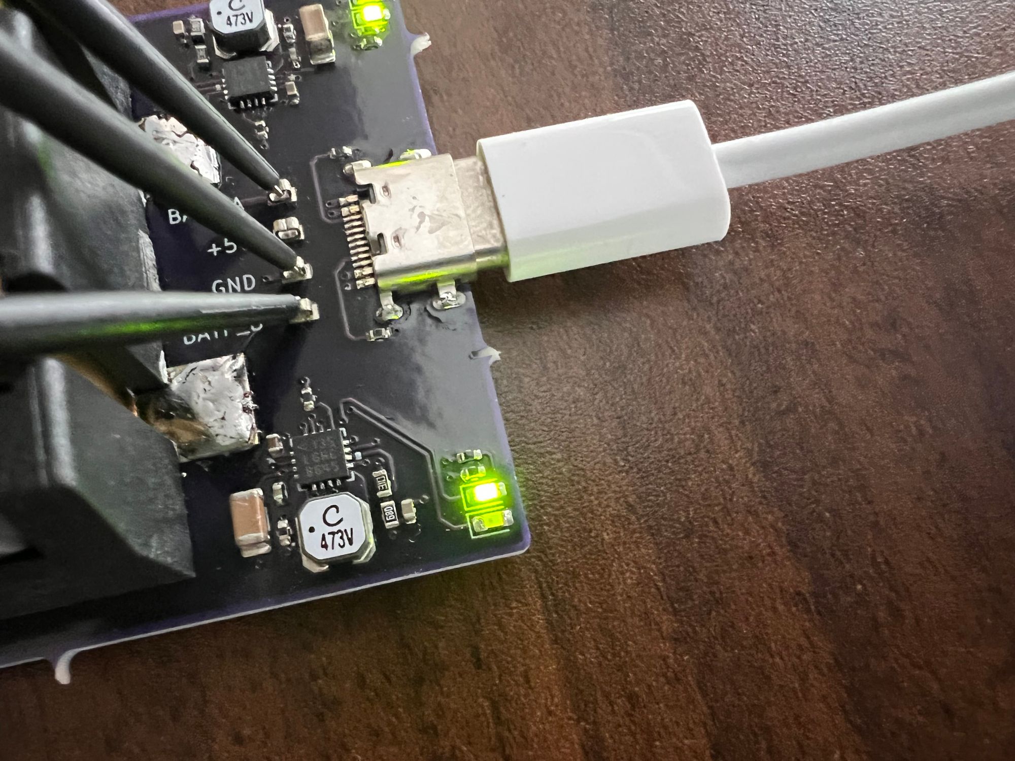
With the analyzer leads clipped on, I set the analog sample rate as low as possible, and left popped in a couple batteries. I was surprised to see just how rapidly the voltage flies from 2.4v to 3.2v here, and was also surprised at how slowly it continued on about 3.4v before the final jump to 3.6v (set by a couple resistors). It's pretty obvious that there isn't much real capacity in that last 0.2 or so volts.
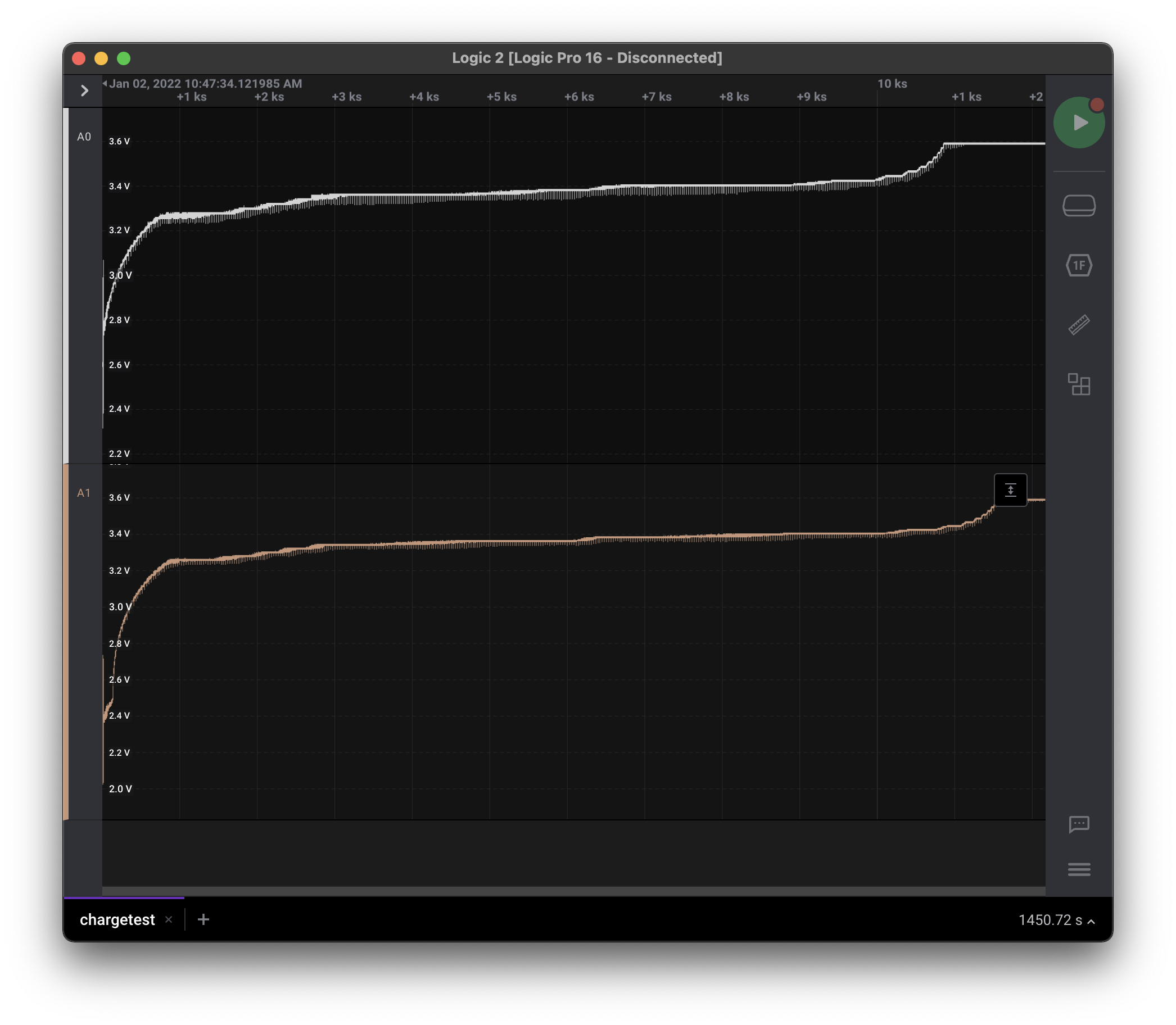
Looking closely at the above screenshot, we see some little drops in voltage every 28 seconds, on the dot.

Each drop lasts exactly 36ms (verified by datasheet). As it turns out, this is when the charging IC unhooks itself to measure the open circuit voltage of the lithium cell. This way it is guaranteed to have a good measurement of the current battery voltage.
Issues
So far, I have only found one issue with the board, which in hindsight was a lazy oversight. The datasheet specifies that if needed you can use a P-FET to prevent battery voltage from flowing back into the supply (USB port in this case). Of course, when designing the board I didn't think I needed this. As it turns out, Apple's (and maybe also some other) USB-C charger bricks check VBUS voltage before enabling power on the USB port. If the batteries are inserted into the charger before pluggin in the USB plug, Apple bricks will never enable power to the charger. I didn't have this problem with any of my other chargers (mostly RavPower banks and bricks). For now, I am inserting batteries after plugging in the USB port with Apple chargers, otherwise it works as designed.
Conclusion
Apart from the laziness on missing a P-FET, the board works great and gets just warm enough to feel like it's working properly. It took me a bit before I felt safe letting this thing out of my eyesight while charging, but now it's a useful tool that lets me take advantage of these LiFePo4 cells. It was also a good intro to KiCad 6, which is leaps and bounds better than previous versions.
