IMU Tester Senior Design Project

The total design report for this project spans 80 pages. I am using this quick post to share some parts of the project I found fun or interesting rather than regurgitating the design report. This project was originally presented at Western Michigan University's 2021 Senior Design Conference at the College of Engineering.


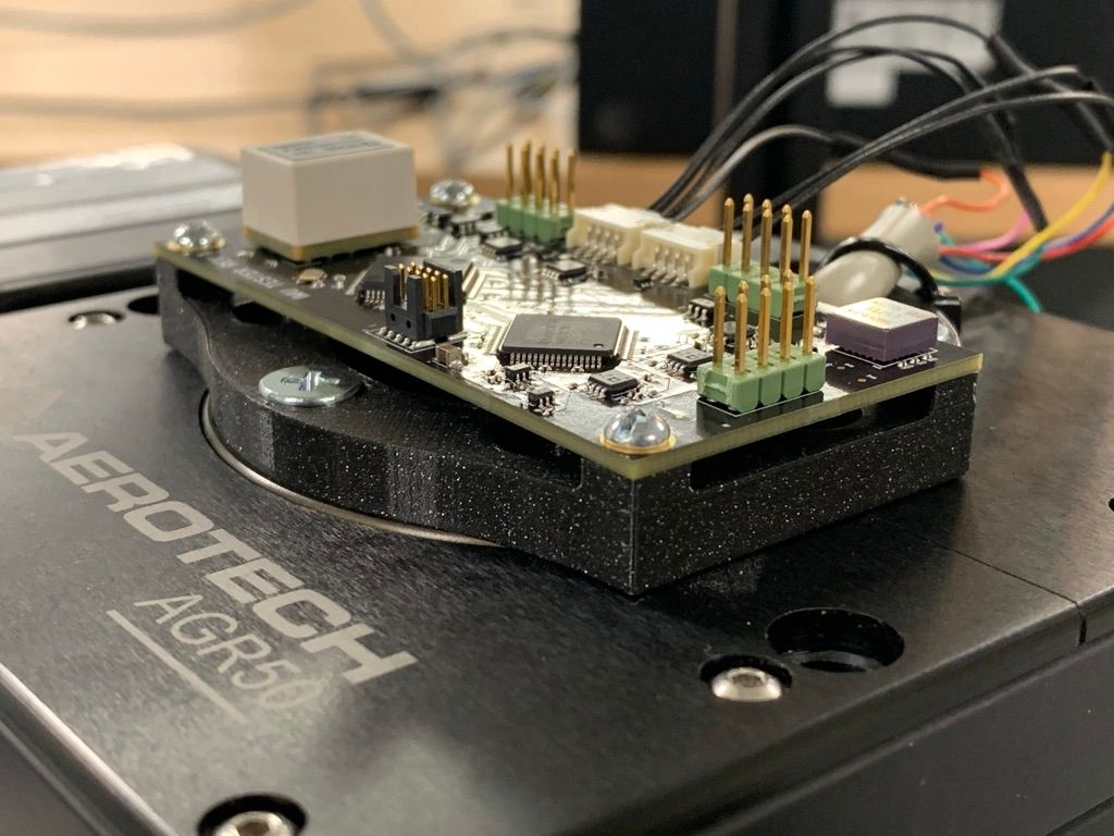
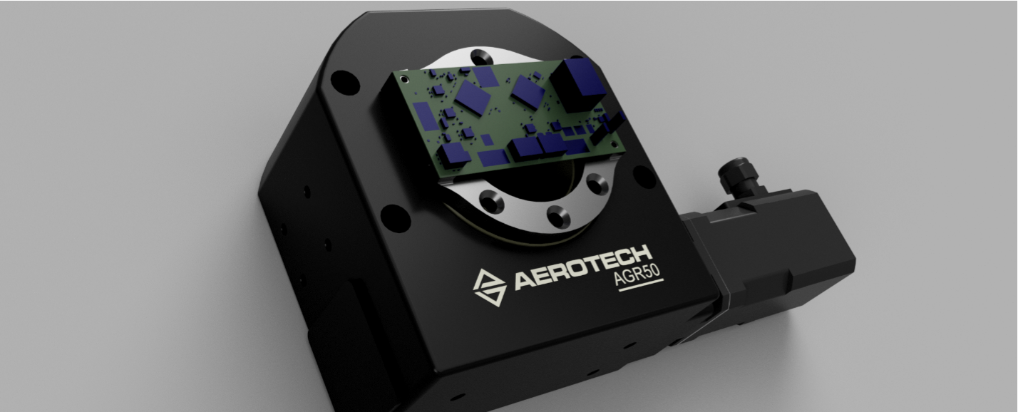
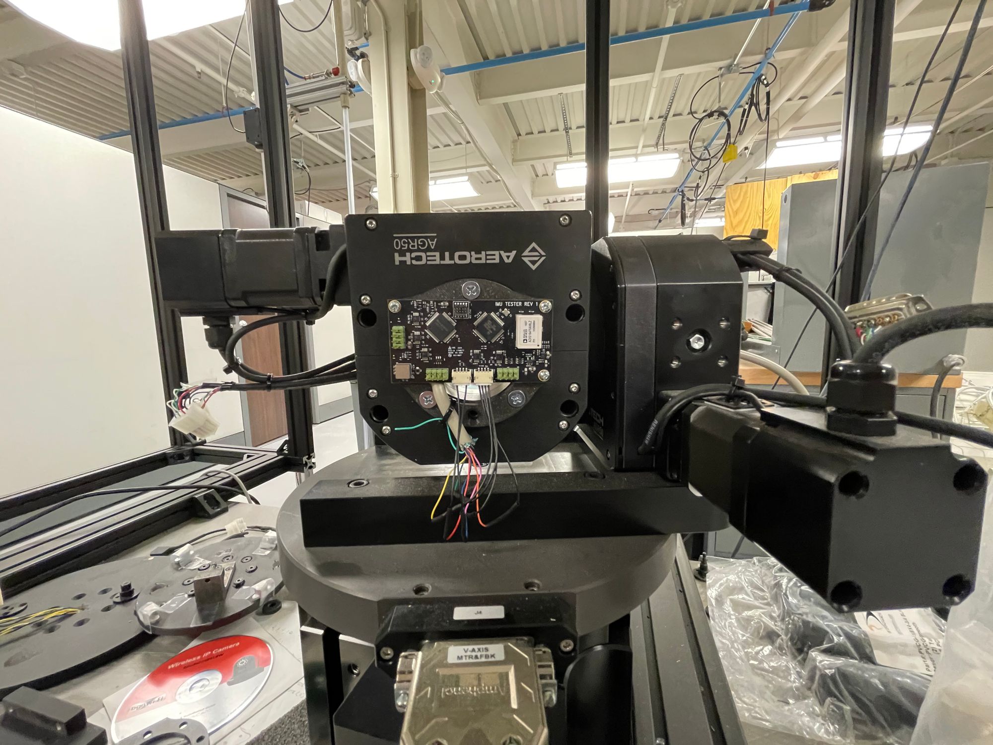
While working as an intern at Stryker, an engineering partner and I designed hardware, firmware, and software to run a fully automated 6 axis IMU characterization and calibration rig. The rig consists of a high speed 3 axis rate table, a PCB housing the device under test, a dummy PCB acting as a transceiver, and a host laptop to control the rate table and log data to MATLAB. The project was kept just under the budget of $5000.


This system needed to log 6 axis data from an ADIS16470 IMU and single axis data from an ADXRS642 gyro + ADS1178 ADC at a 2Khz frame rate, along with some additional data for syncing to the motion system and ensuring data integrity.
// Burst read data format. Holds raw data for checksumming
// all values are in raw 16 bit 2's complement form.
struct burstRead_s
{
    uint16_t	diagStat;

    uint16_t	xGyroOut;
    uint16_t	yGyroOut;
    uint16_t	zGyroOut;

    uint16_t	xAcclOut;
    uint16_t	yAcclOut;
    uint16_t	zAcclOut;

    uint16_t	tempOut;

    uint16_t	dataCntr;

    uint16_t	checksum;

} __attribute__((packed)); // no padding
To keep things simple, we packed this struct up at 2Khz and shot it off over the LVDS link to MATLAB. There, the struct was checked for integrity, unpacked, and plotted in the custom GUI.
Interfacing with the ADIS16470 micro was fun because we needed (ok we didn't actually need to) to do all of the SPI data transfer using the DMA controller. The goal was to write this firmware in a manner that could be used in a real product, so we needed to leave crucial CPU bandwidth available for other tasks. We were using the TI Tiva TM4C due to historical reasons at the company, and with this comes a limitation. The SPI peripheral only has a 16 byte hardware FIFO strapped to it, but we needed to read a 22 byte packet from the IMU during every frame. Normally, we could allow the SPI peripheral to trigger additional DMA transfers after the FIFO is freed, but in this case we were triggering the DMA controller off of the hardware "data ready" pin of the IMU, and the DMA can only have a single trigger at a time.
The way we dealt with this was to implement a delay using the DMA. This is done by adding a couple precisely timed dummy transfers to the DMA control table, burning some time while the first few SPI transfers complete. The icing on the cake is that the final step of the DMA transacation is the set the DMA controller up for the next transaction. The result? A 100% CPU free method of reading high speed data from our IMU. We could literally halt the CPU via a debugger and still be updating internal structs in RAM at full speed. It's my favorite chunk of embedded code I've written so far.
Here's the DMA control table with a large block comment explaining the process.
/**
 *	@brief Perform one time setup for IMU SPI DMA control. Once called, DMA will continue transfers indefinitely.
 *
 * 	@details
 * 	In order to perform all steps without CPU intervention, the DMA must execute delay cycles.
 * 	This is because the SSI TX and SSI RX FIFO's are only 8 uint16's deep, and we need to send 11 u16s per frame.
 * 	In order to solve this without CPU intervention, the following steps are executed in the task table:
 *
 * 	1. Fill SSI TX FIFO with 8 out of the 11 u16s
 * 	2. Dummy transfer in order to spin the DMA until the full 8 u16s are shifted out.
 * 			-- while this occurs, the RX FIFO is filling
 * 	3. Read out the now filled SSI RX FIFO
 * 	4. Place the 3 remaining u16s in the SSI TX FIFO
 * 	5. Spin the DMA while the 3 u16s are shifted out.
 * 			-- while this occurs, the RX FIFO is filling
 *	6. Read out the partially filled (3/8 u16s) RX FIFO
 *			-- at this point the SPI transfers are complete, and memory should have IMU data in it.
 *	7. Set dma.dataReady[0] to 1, to indicate that the transfer is complete.
 *	   It is up to software to crunch the data and set it back to 0.
 *	   This must be a PER (peripheral) based transfer. Otherwise the transfer repeats without the GPIO event.
 *	8. Put this control table back into the DMA controller memory space.
 *	9. Do a 1 byte dummy transfer. This tells the DMA controller that the scatter gather task list is complete because it a UDMA_MODE_AUTO transfer.
 *	   Only the final transfer in the table can be UDMA_MODE_AUTO.
 *
 *	For steps 2 and 5 (dummy transfers) the number of transfers is tied to the number of bits to shift out and the SSI speed.
 *	A good way to check your timing on this is to set a dma.dataReady[0] to 1 immediatly after spinning and do a pin toggle
 *	in the superloop based on that value. Ensure the flip happens after relevant data is fully shifted out by the pin flip.
 */
static tDMAControlTable taskTableSSI[] = {
    uDMATaskStructEntry(8, UDMA_SIZE_16,
                        UDMA_SRC_INC_16, dma.txBuff,
                        UDMA_DST_INC_NONE, (void *)(SSI0_BASE + SSI_O_DR),
                        UDMA_ARB_8, UDMA_MODE_MEM_SCATTER_GATHER),

    uDMATaskStructEntry(1000, UDMA_SIZE_8,
                        UDMA_SRC_INC_8, delayBuf,
                        UDMA_DST_INC_NONE, delayBuf,
                        UDMA_ARB_8, UDMA_MODE_MEM_SCATTER_GATHER),

    uDMATaskStructEntry(750, UDMA_SIZE_8,
                        UDMA_SRC_INC_8, delayBuf,
                        UDMA_DST_INC_NONE, delayBuf,
                        UDMA_ARB_8, UDMA_MODE_MEM_SCATTER_GATHER),

    uDMATaskStructEntry(8, UDMA_SIZE_16,
                        UDMA_SRC_INC_NONE, (void *)(SSI0_BASE + SSI_O_DR),
                        UDMA_DST_INC_16, dma.rxGyroSensorData,
                        UDMA_ARB_8, UDMA_MODE_MEM_SCATTER_GATHER),

    uDMATaskStructEntry(3, UDMA_SIZE_16,
                        UDMA_SRC_INC_16, &(dma.txBuff[8]),
                        UDMA_DST_INC_NONE, (void *)(SSI0_BASE + SSI_O_DR),
                        UDMA_ARB_4, UDMA_MODE_MEM_SCATTER_GATHER),

    uDMATaskStructEntry(800, UDMA_SIZE_8,
                        UDMA_SRC_INC_8, delayBuf,
                        UDMA_DST_INC_NONE, delayBuf,
                        UDMA_ARB_8, UDMA_MODE_MEM_SCATTER_GATHER),

    uDMATaskStructEntry(4, UDMA_SIZE_16,
                        UDMA_SRC_INC_NONE, (void *)(SSI0_BASE + SSI_O_DR),
                        UDMA_DST_INC_16, &(dma.rxGyroSensorData[7]),
                        UDMA_ARB_4, UDMA_MODE_MEM_SCATTER_GATHER),

    uDMATaskStructEntry(1, UDMA_SIZE_8,
                        UDMA_SRC_INC_NONE, dma.dataReadyConst,
                        UDMA_DST_INC_NONE, dma.dataReady,
                        UDMA_ARB_1, UDMA_MODE_PER_SCATTER_GATHER),

    uDMATaskStructEntry(PRIMARY_CONTROL_STRUCT_SIZE, UDMA_SIZE_8,
                        UDMA_SRC_INC_8, dma.txCircularBuff,
                        UDMA_DST_INC_8, &(controlTable[DMA_CH7_PRIM_CONTROL_OFFSET]),
                        UDMA_ARB_16, UDMA_MODE_MEM_SCATTER_GATHER),

    uDMATaskStructEntry(1, UDMA_SIZE_16,
                        UDMA_SRC_INC_NONE, dma.txBuff,
                        UDMA_DST_INC_NONE, dma.rxDummyBuff,
                        UDMA_ARB_1, UDMA_MODE_AUTO)

};
This communication happened without a hitch, running for days without any dropped frames. If this was something to be used in production, we'd have had to think about what to do when a frame drops. Use the last good frame? Extrapolate what the next frame should be based on the last few frames? This ends up being quite the application specific problem.
In the end, we managed to deliver this project a couple weeks ahead of time and the live demos went well. The only casualty was one of the IMUs, which snapped off of the PCBA when the table was commanded to rotate a little farther than it should have. We promptly implemented some software end stops using the table's bundled software.