PDSupply USB-C PD Power Supply

GitHub links:
This is a project I worked on during June of 2020 which ended up being useful for my extracurricular projects (FSAE and my personal stuff).
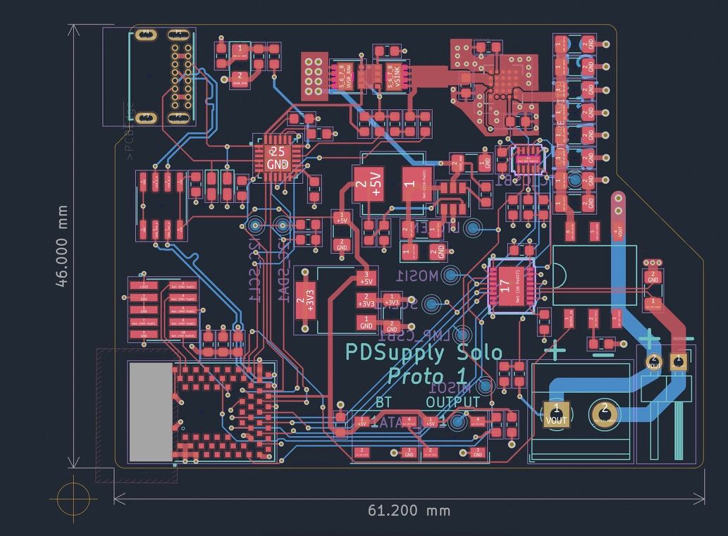
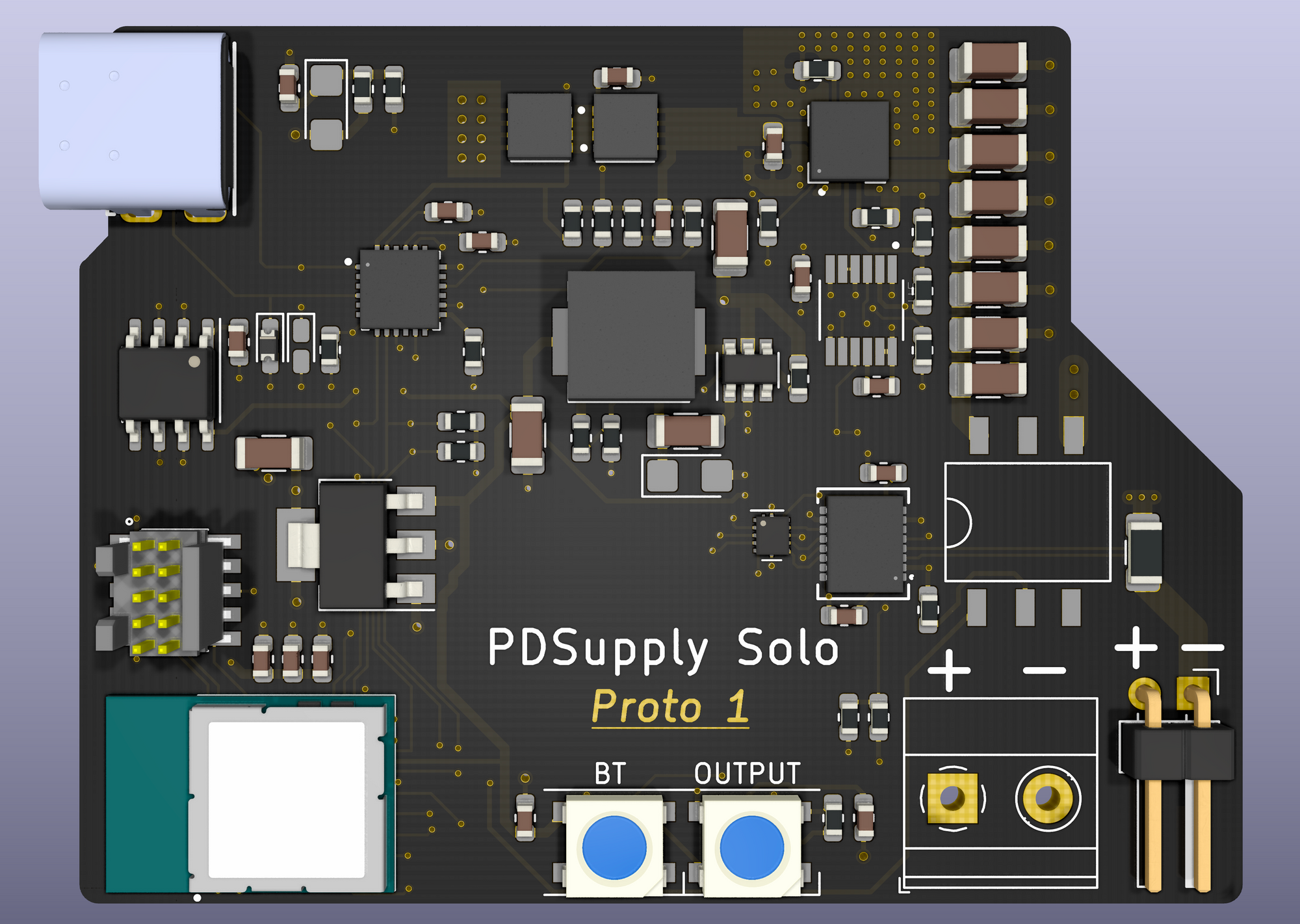
The PDSupply is a USB-C Power Delivery capable adjustable power supply. The board is smaller than a credit card and can output anywhere from 1.2v to 12v @ 1A. It works by negotiating a higher voltage from the USB VBUS rail, and then bucking it down to a more precise voltage adjustable by the user. I designed the board with a current limiting IC, but this ended up not working correctly and had to be removed for the board to actually function. I'll be working on a redesign soon with that and a few other improvements.
Interface

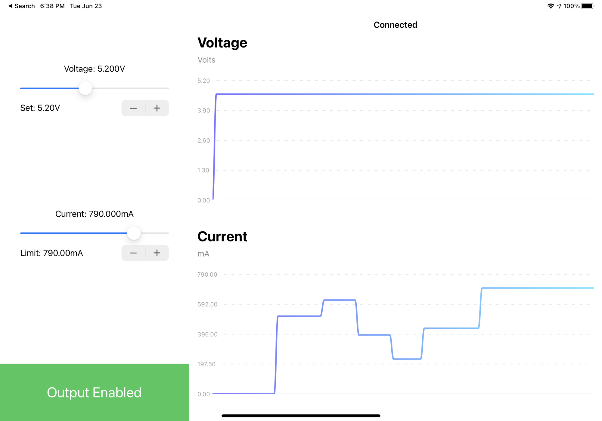
One of my ideas for this project was to focus on keeping the board minimal and handing off all of the controls to a secondary device. In hindsight this was a cool technical challenge but not the best for real world usage. Once I actually started using this thing I realized it would benefit from at least an on/off button to avoid reaching for my phone so often.
I originally wrote the app for use with my iPhone and iPad Pro and was pleasantly surprised when I selected M1 Mac as a compilation target in Xcode and everything just worked. Xcode spat out a MacOS compatible app, complete with working BLE and a scalable UI.
Firmware
The PDSupply project was my first dive into the Nordic Semiconductor NRF52 and the NRF-SDK. After finding the right template project to branch off of (linked in the repo), it was easy to send a struct of data back and forth to an iPhone.
In general, the firmware does these things:
- Update the "central" device (iPhone) every x ms with the latests readings via BLE.
- Read values from the central and use them to command the output voltage and current limits.
- Continuously monitor output current and decide if the output relay should be on.
- Manage USB-PD (when the STUSB4500 isn't running autonomously).
- Manage the LEDs.
// Supply to iPhone, 16 BYTES
struct SupplyData_struct {
	uint32_t counter;
	uint32_t status;
	float measuredVoltage;
	float measuredCurrent;
};

// iPhone to Supply, 16 BYTES
struct ControllerData_struct {
	uint32_t commandedStatus;
	uint32_t commandedOutput;
	float commandedVoltage;
	float commandedCurrent;
};
With these structs, the rest of the firmware can be abstracted away from the Bluetooth bits and simply operate out of the data in these structs. The ControllerData_struct is sent on a timer, notifying the iPhone every time a new value is published.
static void notification_timeout_handler(void *p_context) {
  UNUSED_PARAMETER(p_context);
  ret_code_t err_code;

  SupplyData.counter++;
  memcpy(&dataPacket, &SupplyData, sizeof(SupplyData));

  err_code = ble_cus_custom_value_update(&m_cus, (uint8_t *)&dataPacket);
  APP_ERROR_CHECK(err_code);

  updateStatusLed(SupplyData);

  transferQueued = true;
}
When the iPhone app is notified, it then adds the latest voltage and current measurements into a queue which is graphed for the user to see. This way we can keep a rolling window of old values to graph along with the latest. In the opposite direction, the iPhone simply sends its respective struct when something noteworthy happens, like the user changing the voltage requirement.
On the topic of software, it may be a good idea to have a watchdog of sorts - the iPhone sends a value to the supply every 100ms or so, and if the supply doesn't see a blip for 500ms it shuts off. For now that's not implemented. As it sits, the power supply won't even shut off when the phone is disconnected, which is convenient but may one day be very not convenient.
CoreBluetooth Application
This was the most fun part of this project. After working with firmware, the in depth debugging tools and clean interface that iOS provides was a breath of fresh air. The main Bluetooth controller file exposes a singleton that is used by the UI, and the file itself has a top to bottom life cycle that the CoreBluetooth API hooks into. I even added in little haptics when the supply is turned on or off.
    public func commandSupply(commandedStatus: UInt32, commandedOutput: UInt32, commandedVoltage: Float32, commandedCurrent: Float32) {

        // Mutable values required for passing as pointers
        var _commandedStatus: UInt32 = commandedStatus
        var _commandedOutput: UInt32 = commandedOutput
        var _commandedVoltage: Float32 = commandedVoltage
        var _commandedCurrent: Float32 = commandedCurrent
        // Output data buffer
        var outputData: Array<UInt8> = Array(repeating: 0, count: 16)

        memcpy(&outputData, &_commandedStatus, 4)
        memcpy(&outputData[4], &_commandedOutput, 4)
        memcpy(&outputData[8], &_commandedVoltage, 4)
        memcpy(&outputData[12], &_commandedCurrent, 4)

        if (connected) {
            self.peripheral.writeValue(Data(outputData), for: dataCharacteristic, type: .withResponse)

            if (commandedStatus == PD_COMMAND_OUTPUT_ON) {
                BluetoothController.haptics.poweronHaptic()
            } else if (commandedStatus == PD_COMMAND_OUTPUT_OFF) {
                BluetoothController.haptics.poweroffHaptic()
            }

        }
    }
Here we can see the simple writeValue function exposed by CoreBluetooth which is used to send any arbitrary data to a BLE compatible device.
    public func centralManagerDidUpdateState(_ central: CBCentralManager) {
        if central.state == CBManagerState.poweredOn {
            central.scanForPeripherals(withServices: nil, options: nil)
            print("scanning")
        } else {
            print("bluetooth not available")
        }
    }

    public func peripheralManagerDidUpdateState(_ peripheral: CBPeripheralManager) {
        print("State updated")
    }

    public func centralManager(_ central: CBCentralManager, didDiscover peripheral: CBPeripheral, advertisementData: [String : Any], rssi RSSI: NSNumber) {
        if peripheral.name == pdsupplyName {
            self.peripheral = peripheral
            central.connect(peripheral, options: nil)
            central.stopScan()
            print("PDSupply Found!")
        }
    }

    public func centralManager(_ central: CBCentralManager, didConnect peripheral: CBPeripheral) {
        print("connected")
        peripheral.delegate = self
        self.peripheral.discoverServices([serviceUUID])
    }
The whole API is functional and neatly segments code into steps of the BLE device life cycle from connection to disconnection. You just pop the code you want to run between the right brackets, and the OS will call it when the time is right. For example, in the above code we see that every time we discover a peripheral, the App is told to check the name of the device (not what you should use in production). Once we find the right device, the app will then interrogate it - checking for available services it exposes. It then finally finds the service with all of the power supply data that we set up on the firmware side, and subscribes to its notifications.
Hardware

The PCB is smaller than a credit and worked decently. There a number of things that I would change:
- This was my first time laying out a switcher (old project), so I chose the LTM8074 with an integrated inductor. This is a great part but severely limits the output compared to the 100W input, as it can only flow 1A @12V.
- I used a chunky switcher with an external inductor for the 5V rail which powers some of the other components of the board, and in hindsight that was a bad decision. This is a better application for the 8074.
- Current limiting didn't work, and the board only functions when the IC is removed.
- I2C with the STUSB4500 was finicky due to some issue with assembly.
- Switching noise was audible via the capacitor bank on the right side. This may be as simple as low quality caps, or something more.
Apart from those issues, this board was capable of outputting 1.2-12V @ 1A, while getting fairly hot in the process. The STUSB4500 worked well in "headless" mode. I programmed it one time to favor 20V @ 5A from the source, backing down to 9V @ 2A if that was not available. Due to the finicky I2C comms, I was unable to control this on the fly with via the main NRF52 microcontroller.
I had the boards assembled by PCBWay for a total cost of about $400 for two boards. This wasn't the best deal but I figured it was worth it to give the boards the best chance of working. Unfortunately, both LTM8074s were soldered incorrectly with BGA balls shorted under the package (measurable via dmm). I was able to remove the parts with a hot air gun and replace them after cleaning the area to get both boards to work successfully. I know that these board houses don't typically love doing BGA parts, might be best to avoid them unless an x-ray step is specified.
Usability
In closing, the PDSupply was good as a first attempt at a portable power supply. Although the current limiting didn't totally work as I wanted it to, I still use it often with somewhat proven devices that I know won't immediatly explode upon power application. When I do a redesign with working current limiting, more power capabilities, and working current limiting, I'll link to it here.
WIP of the new design:
