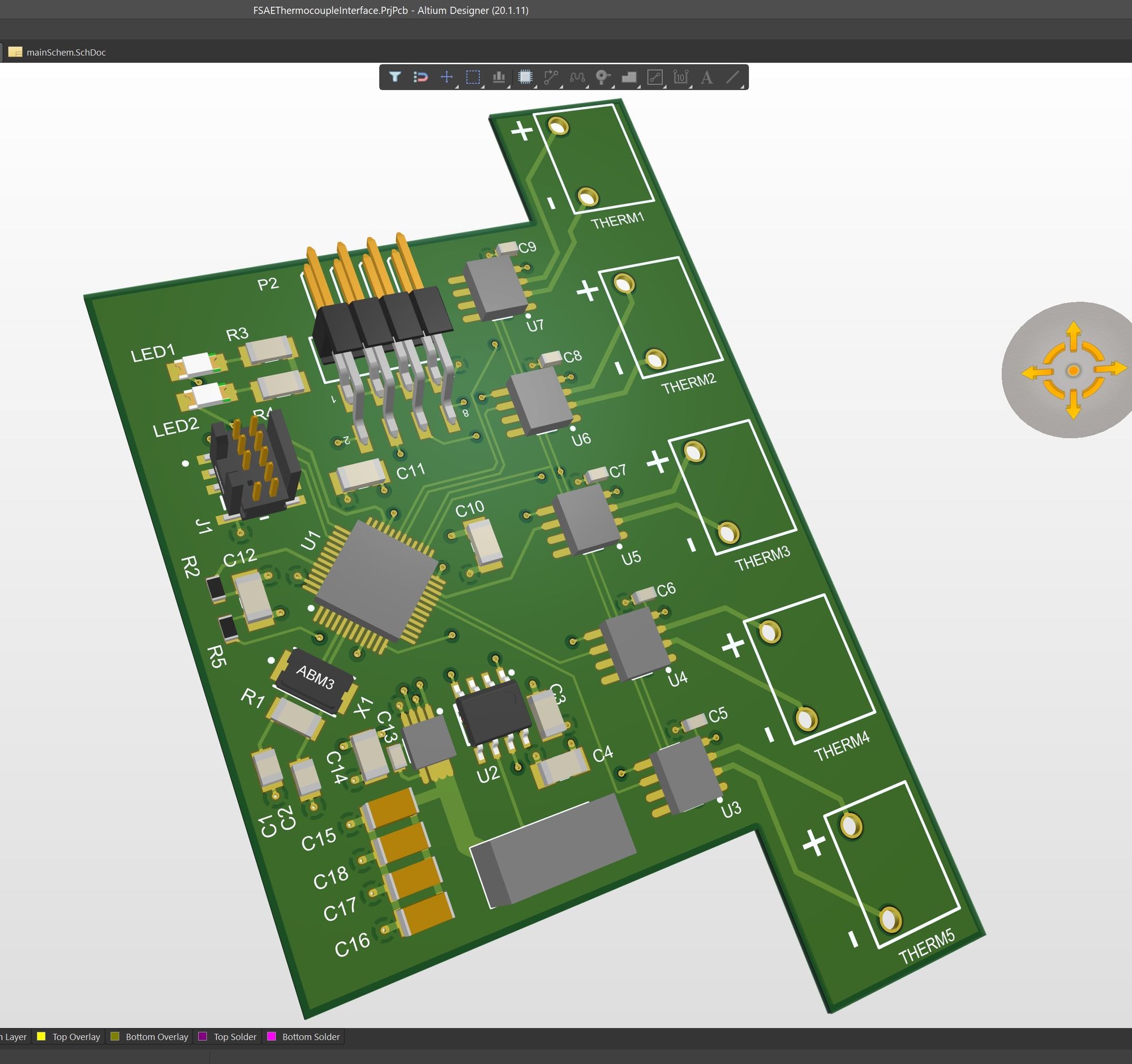
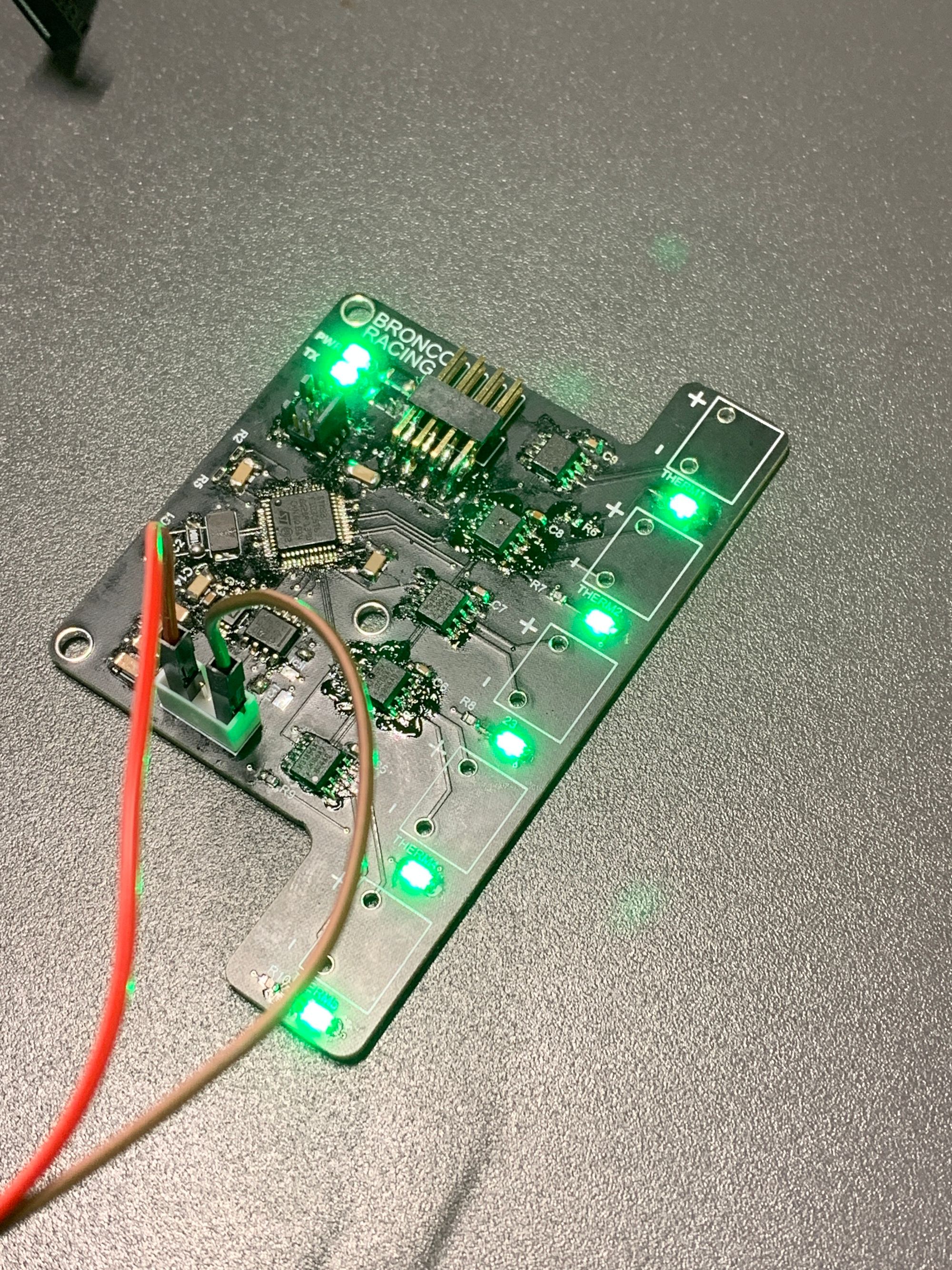
5 Channel Thermocouple to CAN Bridge

This is a super simple device, with moderately bad routing. If I was to remake this board I would downsize the decoupling caps and place the main crystal closer to the MCU. I designed this board during college for my FSAE team, as we needed a way to simultaneously measure 4x exhaust gas temperatures (EGTs in the car world) to ensure all 4 cylinders of our CBR600RR engine are burning in a similar manner. There's an additional 5th channel that is used to measure the average EGT at the collector where all four exhaust pipes converge.
The main component here is the MAX31855K thermocouple to SPI amplifier. This thing includes the ADC, cold junction compensation, and a SPI interface where I can just ask it nicely for the data.


All five amps are simply dropped onto the same SPI bus, and then connected to the STM32. Note there is no MOSI/COPI pin as the MAX31855K is a read only device. It only takes 14 bits to pull the hot side data from the 14 bit amplifier.
The STM32 acts as a bridge to the CAN bus, continuously polling the amplifiers and dumping the resulting data to the race car's CAN bus, to be picked up by the telemetry system located on the nose of the car.
Here is the code that reads the thermocouples and broadcasts the data:
// inside superloop
if (timer.read_ms() >= CAN_MSG_PERIOD_MS) {
  readThermocouples();
  sendCANmessages();

  timer.reset();
  timer.start();
}

// Reads each thermocouple channel and populates output array
void readThermocouples() {
  for (int i = 0; i < NUM_CHANNELS; i++) { // loop through all MAX31855K thermocouple amps

    // get value
    if (maxArray[i].ready()) {
      uint16_t tempBits = maxArray[i].read_temp();
      // MAX31855K indicates errors are values > 2000
      if (tempBits < 2000 && tempBits > 0) {
        // value is good
        tempArray[i] = ((tempBits * (9.0 / 5.0)) + 32.0); // convert value to F
        ledArray[i].write(1);
      } else {
        // value is bad
        // set breakpoints here to find issues
        switch (tempBits) {
          case MAX31855_ERR_NO_TC:
            ledArray[i].write(0); // turn off LED corresponding to thermocouple
            break;
          case MAX31855_ERR_SHORT_GND:
            ledArray[i].write(0);
            break;
          case MAX31855_ERR_SHORT_VCC:
            ledArray[i].write(0);
            break;
          default:
            ledArray[i].write(0);
            break;
        }
        // indicate error by setting value to 0
        tempArray[i] = 0;
      }
    }
  }
}

// Fill and send CAN messages, MSByte first
void sendCANmessages() {
  outMsgA.data[0] = (tempArray[0] >> 8) & 0xFF;
  outMsgA.data[1] = tempArray[0] & 0xFF;

  outMsgA.data[2] = (tempArray[1] >> 8) & 0xFF;
  outMsgA.data[3] = tempArray[1] & 0xFF;

  outMsgA.data[4] = (tempArray[2] >> 8) & 0xFF;
  outMsgA.data[5] = tempArray[2] & 0xFF;

  outMsgA.data[6] = (tempArray[3] >> 8) & 0xFF;
  outMsgA.data[7] = tempArray[3] & 0xFF;

  outMsgB.data[0] = (tempArray[4] >> 8) & 0xFF;
  outMsgB.data[1] = tempArray[4] & 0xFF;

  // If message is successfully pushed to CAN FIFO, toggle LED.
  // Note: this does not mean the message made it to the CAN bus
  if (can.write(outMsgA) && can.write(outMsgB)) {
    txLED = !txLED;
  } else {
    txLED = 0;
  }
}
sendCANmessages() could be cleaned up to remove code repetition, but I wanted this code to be approachable by people new to CAN and found it easier to explain when it was all explicitly typed out.

This board worked great and was used on multiple dyno days, and even pointed out some fueling issues that led to incomplete fuel burn, and therefore colder cylinders. We were able to modify the control map on the ECU to individually compensate on these cylinders to bring all four cylinders within a few degress of each other and fully burning their allotted fuel.